RPi and STM32F4Discovery
This is a very brief description of how the STM32F4DISCOVERY board,
with the addition of a couple of very cheap components, can be used as
a Real Time Clock ( RTC ) for the Raspberry
Pi.
With a little extra effort, you get to use the excellent analog to
digital converters, digital to analog converters, SPI, I2C and CAN
interfaces - an ideal platform for teaching electronics, programming,
automation and control for not much more than £10.
I have used software from the fantastic ChibiOS
project which provides a Real Time Operating System ( RTOS ) for this
board and many others. In addition to providing the RTOS, the project
also provides drivers for the microcontroller peripherals and several
example projects, making it very easy to get started.
The project was compiled with tools and a compiler from the Yagarto project.
Hardware
You'll need a fine tipped soldering iron, some solder and these items
from Farnell:
STMICROELECTRONICS
- STM32F4DISCOVERY - BOARD, EVAL, STM32F4-DISCOVERY Order Code: 2009276EPSON
TOYOCOM - MC-306, 32.768KHZ, 6PF - CRYSTAL, MC-306, 32.768KHZ, 6PF
Order Code: 1712823
MULTICOMP
- MCCA000925 - CAPACITOR, 0603, NP0, 10V, 6.8PF Order Code: 1856077RLPANASONIC
- CR-2032/BN - CELL, LITHIUM COIN, 220MAH,3V,2032 Order Code: 5219590
MULTICOMP
- CH7410-2032LF - BATTERY HOLDER, SMT, 20MM Order Code: 2064724
If you haven't got suitable wire, you might need some:
PRO
POWER - 100-30G - WIRE, KYNAR, 30AWG, GREEN, 100M Order Code: 1202483
If you haven't got suitable USB leads then you might need:
MULTICOMP
- SPC20060 - USB 2.0 CABLE ASS, CONNECTOR A Order Code: 1651027
MOLEX
- 68784-0001 - CABLE ASSEMBLY, USB A TO MICRO USB B, 1M Order Code:
1617585
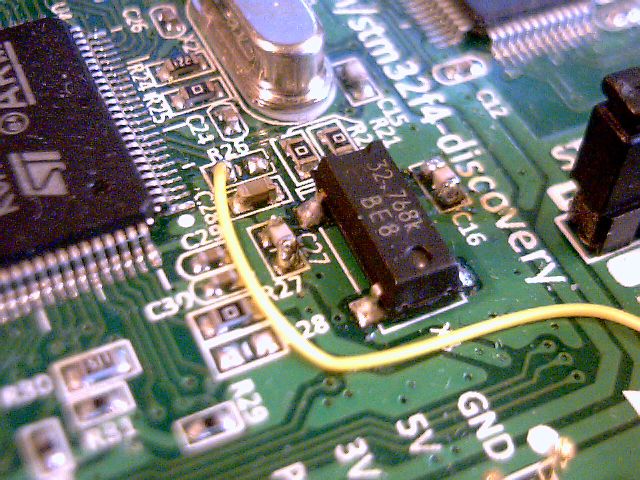
Try and work on an antistatic surface if possible. Remove R26. Fit the
6.8pF capacitors into the C16 and C27 footprints. Fit the crystal into
the X3 footprint. See the picture below:
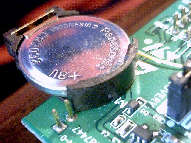
Scratch a little patch of the solder resist away from the ground plane
on the board so that you can see the copper and tin it. Tin and then
solder the negative terminal of the SMD battery holder, through the
holder, onto the board. See the picture below.
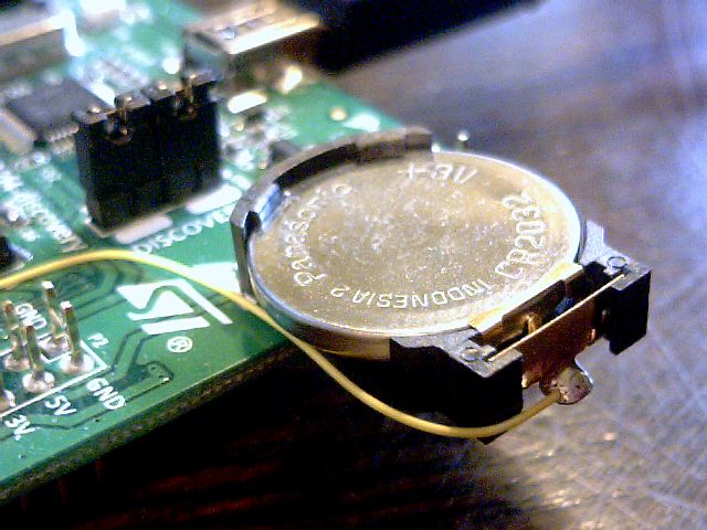
Don't fit the battery yet, even though it is in the picture. Solder the
Kynar wire to the positive terminal of the battery holder. See the
picture below.
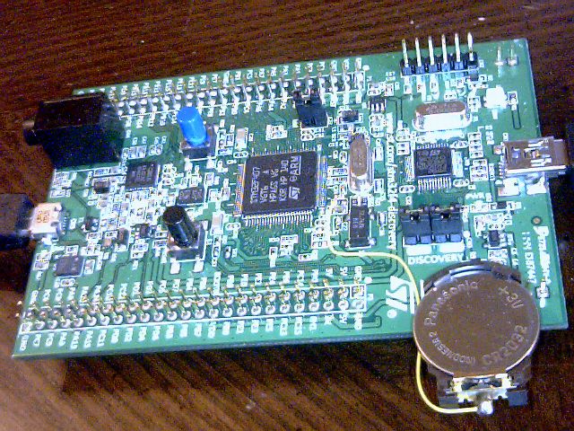
Solder the older end of the wire to the pad in the footprint of R26
indicated in the picture above.
You should have something looking like the picture below.
Software
I did this on Windows XP SP3 but this could be done on the RPi itself
including the downloading to the board as openOCD now supports the
STM32F4DISCOVERY onboard programming hardware.
Download and install the Yagarto
tools and toolchain. When you install them, make sure there are no
spaces in the path e.g. C:\Yagarto.
You can get the latest development version of ChibiOS
here.
Unpack it somewhere but it might be worth avoiding spaces in the path again..
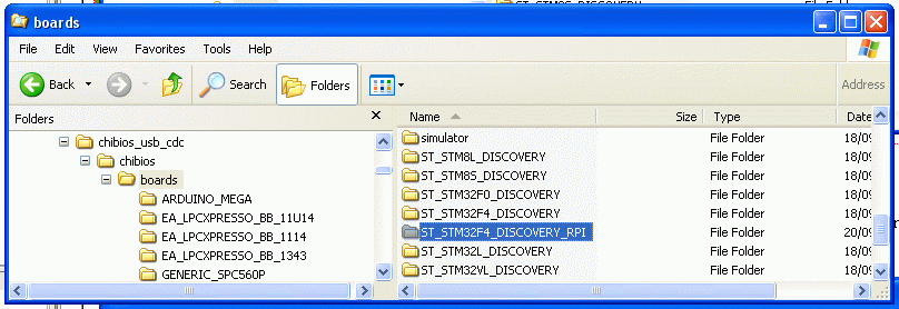
Download this and unpack it
in the "boards" folder. It is modified to show the presence of the
32768Hz crystal. Compare it with the normal ST_STM32F4_DISCOVERY folder
using WinMerge to see the differences.
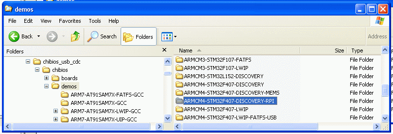
Download this and
unpack it in the "demos" folder. I have taken and modified the
ARMCM4-STM32F407-DISCOVERY-MEMS demo which appears to be a serial port
when you plug the board into a PC or RPi. I have added a little code
taken from the chibios\testhal\STM32F4xx\RTC folder which is able to
set and read the real time clock. WinMerge will be able to show you the differences.
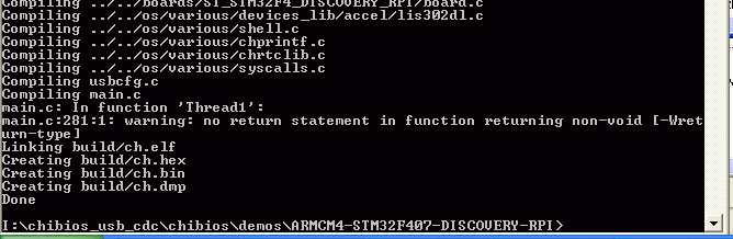
Fire up a command prompt and navigate your way in to the
ARMCM4-STM32F407-DISCOVERY-RPI folder. Type "make" and it should
compile just fine. The command prompt should look something like this:
You'll need the "ch.hex" file which was created in the "build"
subfolder. You'll need this
to program the hex file into the board. You probably ought to upgrade
the firmware using this
and you'll need the driver so
that Windows recognises the board for programming purposes. The mini
USB connector is for power and programming. The micro USB connector is
directly connected to the micro under software control.
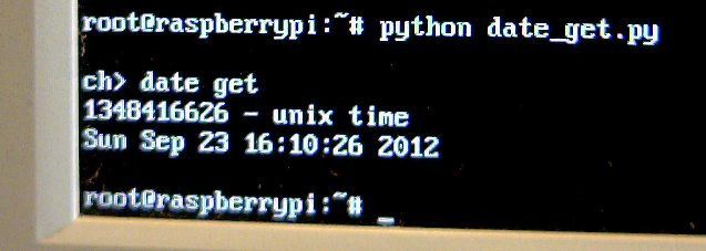
Having programmed the board, the RPi will automatically recognise the
micro USB connector as a serial port ( /dev/ttyACM0 ). You can access
this, as root, with minicom
(type "date get" and "date set") or try a bit of incompetent Python
having done an "apt-get install python-serial":
import serial

rpi=serial.Serial("/dev/ttyACM0",timeout=1)

rpi.open()

rpi.write(\rdate get\r")

line1=rpi.readline()

line2=rpi.readline()

line3=rpi.readline()

line4=rpi.readline()

rpi.close()

print line1,line2,line3,line4
I'm afraid I haven't integrated this into the boot scripts yet.
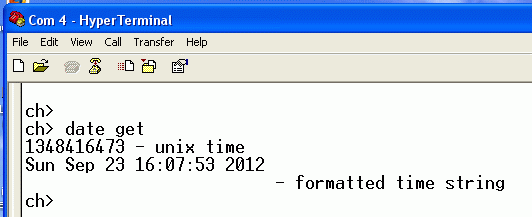
If you want to test this on Windows, you'll need this driver
so that Windows recognises the board as a serial port. When prompted
for the driver files they are to be found in "C:\Program
Files\STMicroelectronics\Software\Virtual COM Port Driver". You can
then use Hyperterminal to type the "date get" and "date set" commands.
Other commands can simply be added to access the other peripherals
using the drivers and example code within the ChibiOS distribution.
Good luck!!